50dB HF RF Sampler

I’ve been using the LPC1 RF Sampler that came with my LP100A wattmeter to sample RF to my Spectrum Analyzer. This is an extremely high quality sampler. However, I can’t use my wattmeter while using the coupler as a sampler.

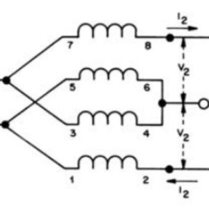
Thus this project was born to build a high quality “lab grade” RF Sampler. Following the design notes in this article from W5QN, I got started.

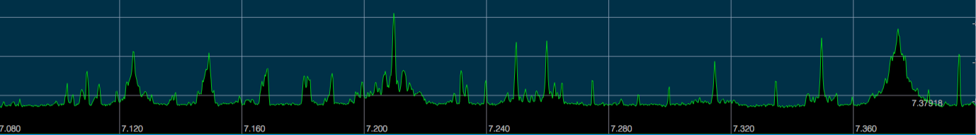
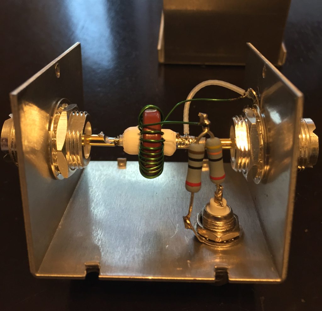
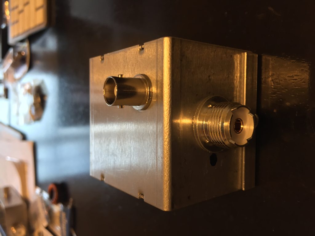
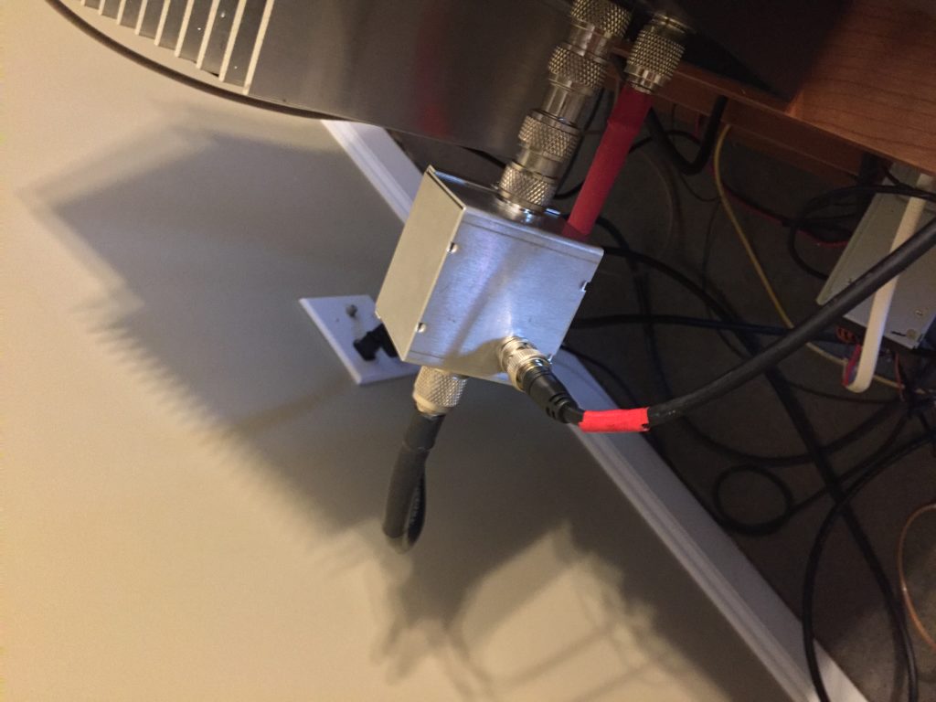
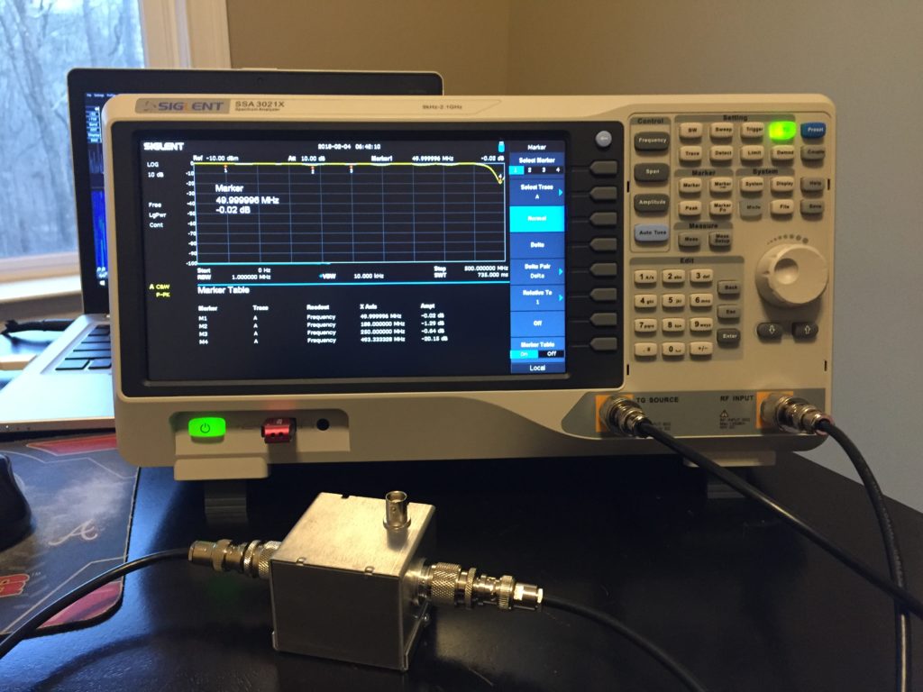
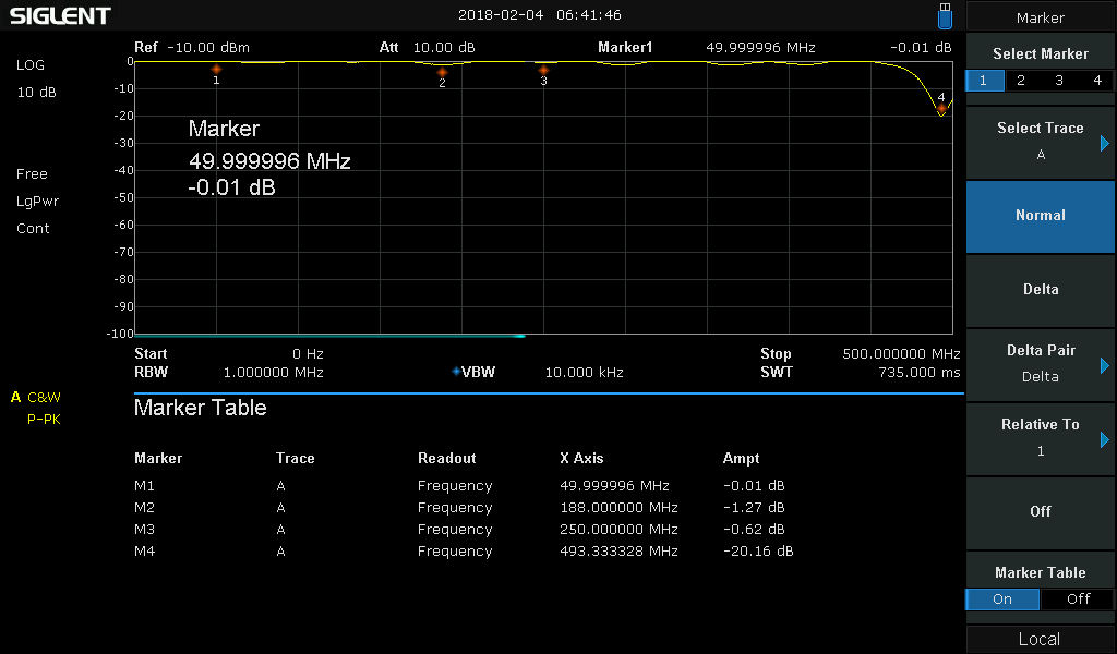
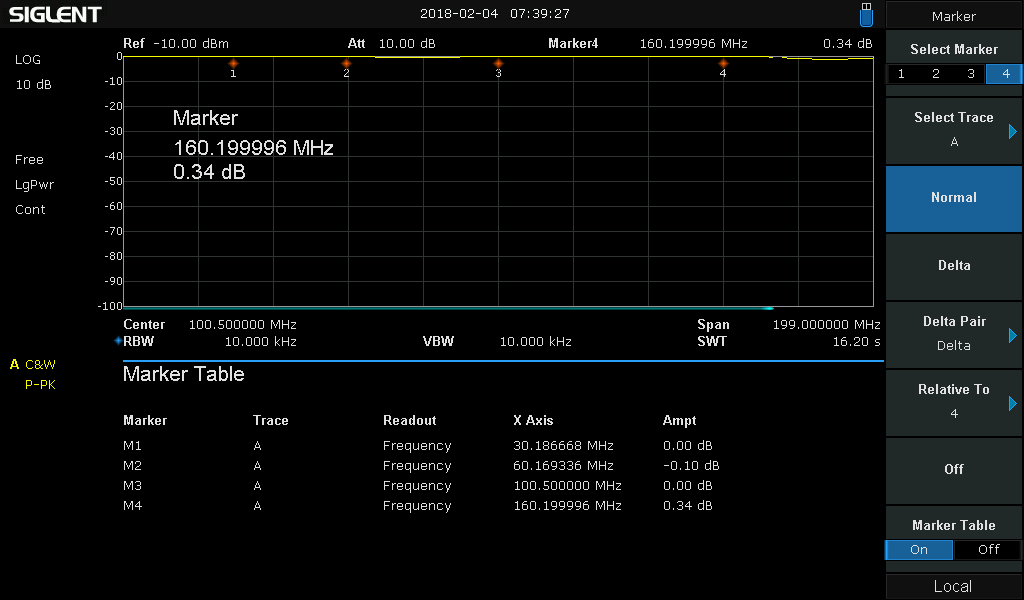
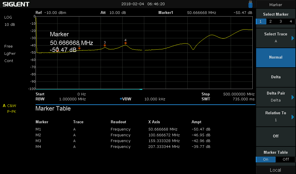
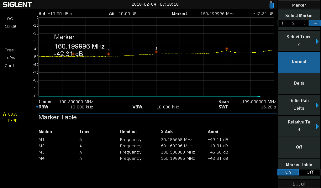
I ended up with a nice compact RF Sampler, capable of 1500W or more, which hit the 50dB design goal dead nuts with nearly 0dB insertion loss.

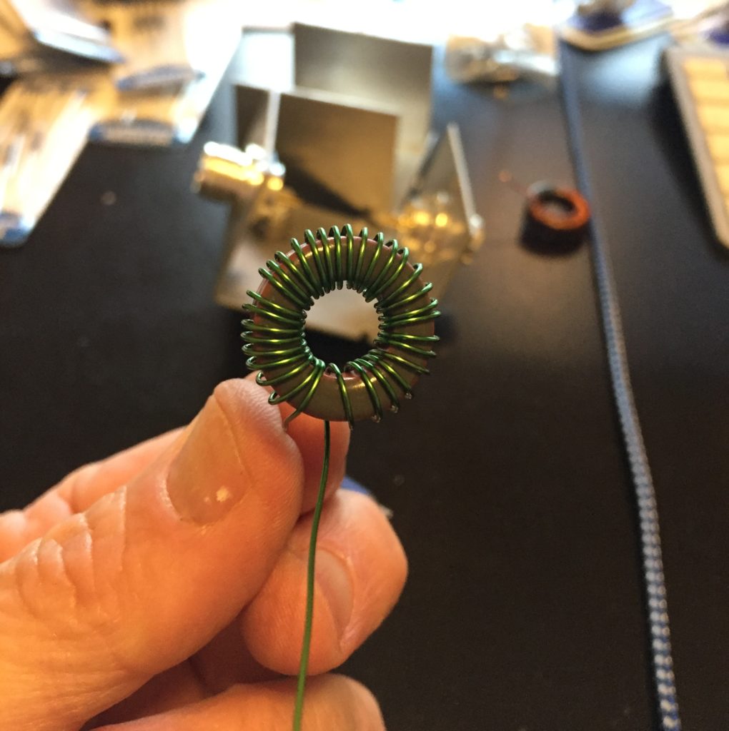
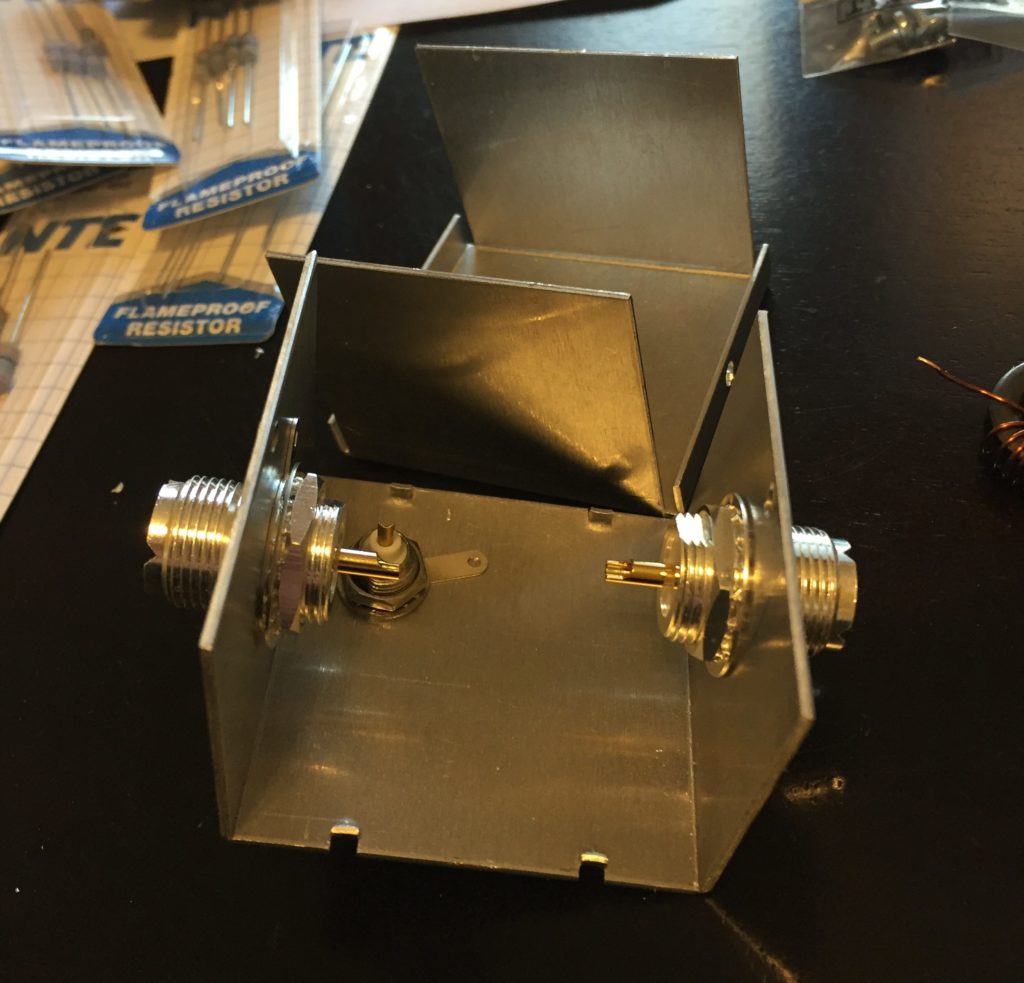
Just going to make this one a pictorial.

T68-2 wound with 32 turns


RF Sampler Mechanicals


RF Sampler Internals


RF Sampler Finished Enclosure


RF Sampler Casework


RF Sampler Inline


RF Sampler Test Setup with Spectrum Analyzer


RF Sampler Insertion Loss to 500Mhz


RF Sampler Insertion Loss to 200Mhz


RF Sampler Attenuation Curve to 500Mhz


RF Sampler Attenuation Curve to 200Mhz


Comments

21 responses to “50dB HF RF Sampler”

  1. Trent Avatar
    Trent

    Nice rf sampler,if u put ferrite in it instead of powered iron do u think it would work better at 200MHz and over

    1. N4GA - Rob Avatar
      N4GA – Rob

      Trent,

      Thanks for the question. I checked with the original designer of this circuit when I was building it and the best way to improve it’s performance in that range is to reduce all the lead sizes to as close to zero as possible. If you crack open a commercial sampler, you’ll see precision SMD components on a impedance controlled PCB with almost zero length traces.

      G’day VK7!

      🙂

  2. Barry G. kery Avatar

    What are the resistor values. Yes, I can figure out color codes but I can not tell what the colors are? I see the black and red, buy can’t tell the other colors?
    Barry, KU3X

    1. N4GA - Rob Avatar
      N4GA – Rob

      Hello Barry,

      Supposed to be 10 ohms and 40 ohms. I have 10 ohms and 43 ohms.

      Check the link to the original article for a lot more details provided.

      Thanks for the comment!

  3. Larry Avatar
    Larry

    Great work Rob!

    Tnx for sharing your good work

    Ur amp is vy fb

    73 and good luck,
    Larry ns4q

    1. N4GA - Rob Avatar
      N4GA – Rob

      Absolutely Larry!

      73s!

  4. Frank Howell Avatar

    Nice post! A follow up question….

    I noticed that you used a different ferrite core and apparent gauge wire. What was the (thicker) wire gauge? Any particular reason you used the T68-2 core? Was the inductance at the 5 uH value in the reference article?

    Thanks for your nice illustrations!

    73

    1. N4GA - Rob Avatar
      N4GA – Rob

      Frank, how are you.

      I’m pretty sure my enamel wire was 24 ga. No particular engineering-based reason I used that 68 core, I just wanted to build with parts that I had on hand here. Lots of variations will work, it just affects the attenuation, assuming you are not overloading the core.

      73s!

  5. Paul Christensen Avatar
    Paul Christensen

    Be careful when using small-core samplers with adaptive predistortion techniques (e.g., ANAN PureSignal). I constructed the same sampler on a Micrometals T44-2 core. At the 500W level on 160m, core saturation occurs and manifests as IMD. The adaptive predistortion algorithm is then not only trying to correct PA non-linearity, but also core non-linearity — and they may be moving in different directions.

    Although the core is not overheating, it is saturating. As such, I’ve gone back to using a balanced capacitive voltage divider for use with adaptive predistortion. Details on my QRZ page.

    The division results in a 50 dB coupling factor. Flatness is not as good as the toroid core sampler, but it’s perfectly acceptable since the response only needs to be flat within the transmit passband. Still the -50 dB port of the cap divider is only down -5 dB at 50 MHz, referenced to 30 MHz. It’s a good trade-off for this purpose as the cap divider introduces no RF non-linearity.

    Paul, W9AC

    1. N4GA - Rob Avatar
      N4GA – Rob

      Interesting points, thanks for sharing. Totally agree that if you are using this attenuator as a feedback voltage divider, it needs to be linear and not have a frequency dependent transfer function within the passband you are attempting to make linear.

  6. Alex Avatar
    Alex

    Would just few turns of wire work as a RF pickup?

    1. N4GA - Rob Avatar
      N4GA – Rob

      For RF detection yes. But you wont get the volage level or bandwidth you need for a general purpose sampler/attenuator with just a few turns of wire.

  7. Steve WX2S Avatar
    Steve WX2S

    Did you also use RG-402? If so, where did you get it from?

    1. N4GA - Rob Avatar
      N4GA – Rob

      Steve,

      I did. Can’t remember where I got it, possibly eBay. You only need an inch or so. If you like I cans send you a couple inches.

      Rob

      1. WX2S Avatar
        WX2S

        Amazon sells RG-402. I was wary of it, but it seems like the real thing. I can solder to the braid. I attempted to melt the insulation with a soldering iron to see if it was polyethylene, but it wouldn’t melt, so it’s probably real PTFE. The center conductor can be easily stripped with a 20-gauge (or so) wire stripper — no need to mess with X-Acto knives.

  8. Steve WX2S Avatar
    Steve WX2S

    Forgot the link: https://www.amazon.com/dp/B00VPRF40I

    Seller: Custom Cables Group LLC

    About enough to make 20 couplers.

  9. Steve WX2S Avatar
    Steve WX2S

    Found it on Amazon.

    https://www.amazon.com/dp/B00VPRF40I

    Seller: Custom Cables Group LLC

    About enough to make 20 couplers. Seems like the real deal. The inner insulation doesn’t melt when heated with a soldering iron, so it’s probably Teflon rather than something cheaper.

    I found I could strip the center conductor cleanly with a pair of 20ga wire strippers, so no need to mess with X-Acto knives.

  10. Steve WX2S Avatar
    Steve WX2S

    W5QN recommended testing for coupling between the high-power side and the resistor network before installing the toroid. I did this and found some coupling. A Faraday shield made from some circuit board cured that.

  11. Bryan Watson vk7kwb Avatar
    Bryan Watson vk7kwb

    Hi Guys
    I am a 76 year old amateur and still cant get my head around using an attenuator in line with transceiver out put and getting results like -6.6 dB
    I am using a 50 dB attenuator inline from transceiver @1296Mhz 3 Watts = -17.2 dB at RF meter
    and when the RF amplifier is switched in I get -6.6 dB ??????

    1. N4GA - Rob Avatar
      N4GA – Rob

      Could be a voltage vs power mix-up?

      Or 1296Mhz tresting your attenuator like a stripline.

      I’m not well versed on microwave frequencies, sorry!

  12. Paul Christensen Avatar

    Ignore my previous comment about core saturation on 160m. The root cause was identified after my last post. Unknown to me at the time of measurement, a DX Engineering RG5000HD receiver guard was responsible.

    I had recycled an RG400 sample cable thinking that it was one continuous length. I neglected to eye-witness the cable from end-to-end. But there it was, the RG5000HD under the operating table and the cause of high IMD readings on 160m. A look at the RG5000HD datasheet and overload graphs explains the reason for measurement error.

    -Paul, W9AC

Leave a Reply

Your email address will not be published. Required fields are marked *