LDMOS Amplifier Testing Setup

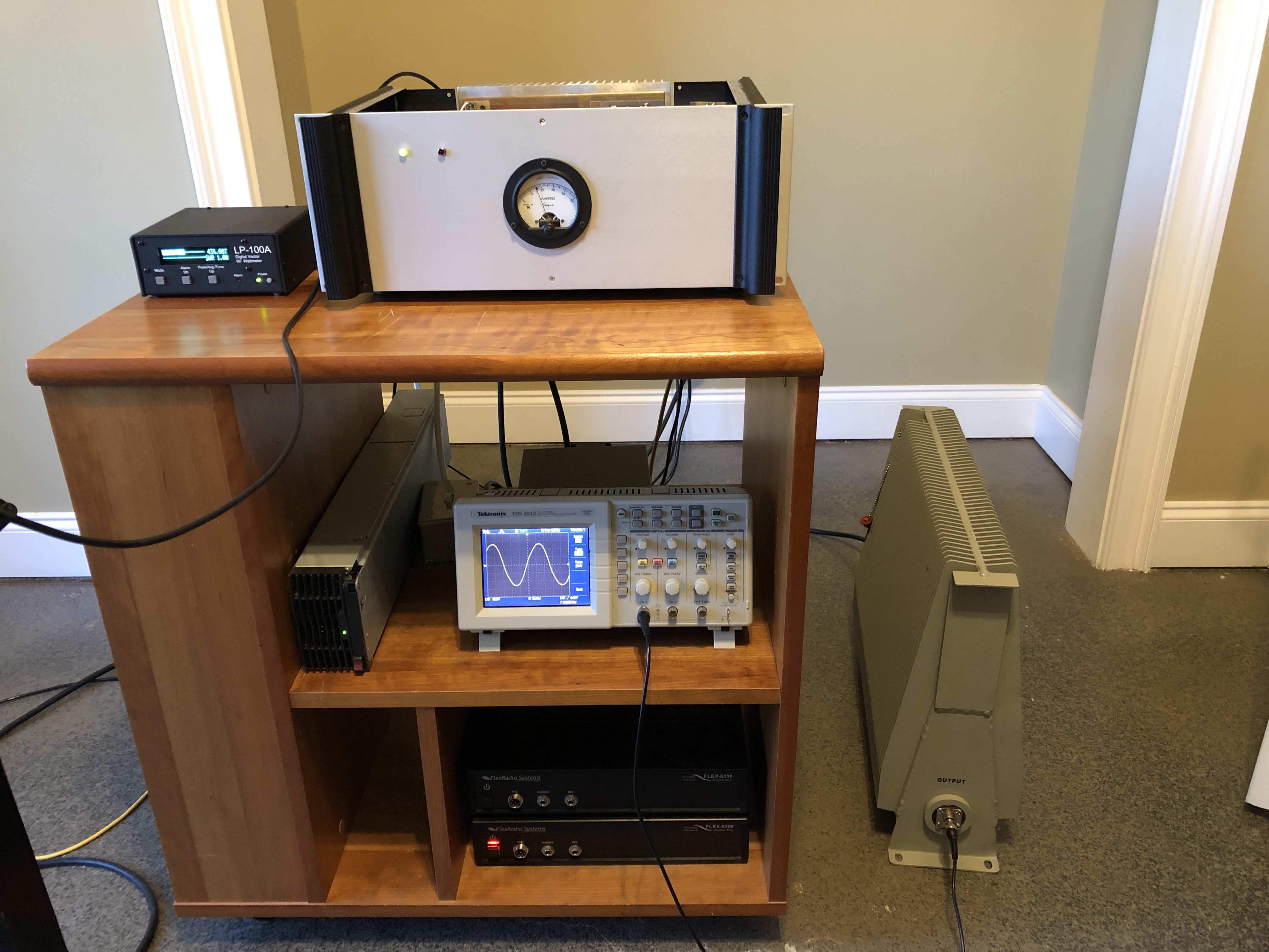
Here’s the testing setup. The enclosure is “universal” and different pallets get dropped into it. In the pic you can see the exciter (Flex 6300), spectrum analyzer, power supply, dummy load, RF power meter, ammeter and oscilloscope. Hiding in the back is a inline RF sampler.

The way I test and develop these amps is very unique. Most individuals and professional amplifier companies try to produce 1500W+ then filter the harmonics down to FCC spec with the LPF on the back end.

This method is extremely easy and does sell amplifiers, since hams only care about watts…and how cheaply they can get them.

Those commercial amplifiers are not really linear by any stretch of the imagination. If you could see what happens to your pretty little sine wave at 1500W, you would be like, “what the crap!”

If any amplifier was truly linear, it would not even need a LPF. I’ll do another whole post on this topic the near future.

Here’s one of my single device pallets running at 500W with perfect (looking) sine waves with no LPF. It will do this to ~600W.

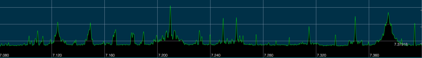
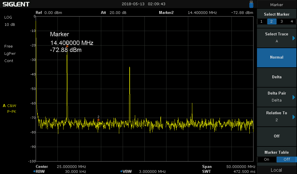
I test my amps with no LPF, full power into a dummy load. I watch the sine waves and watch the spectrum analyzer, primarily the 3rd harmonic. The 3rd tells the story.

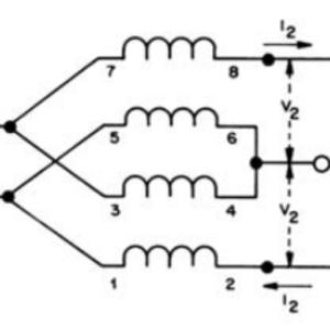
I’ll do another post on this as well, but just so you know, for a single 188XR device amp running at 50V with a 9:1 TLT, the maximum theoretical output to remain in class AB is 733W. Anything above that and the waves take on all sorts of predictable non-linear shapes and the harmonic content rises to unbelievable levels – like 3rd harmonics only -10dB! This is NOT linear.

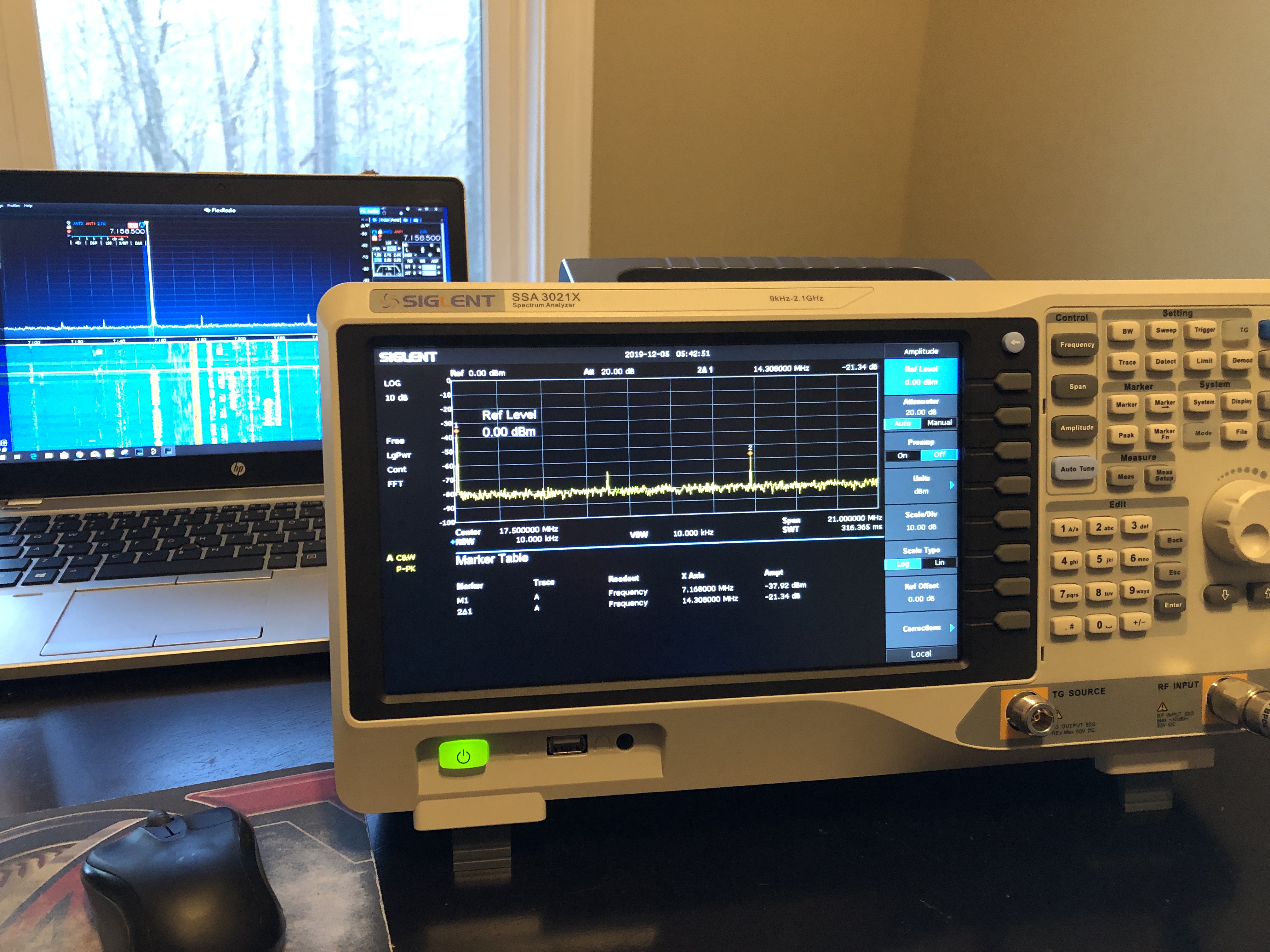
Here’s the same single device pallet as above running at 500W showing the 3rd harmonic down -21dB with no LPF. So there’s 3.97W going out on the 3rd harmonic.

Perfect, heck no, and I’m working to get this even lower.

Better than everyone else’s -10dB 3rd harmonic…which is 50 Watts?!

Heck yeah!!

Comments

34 responses to “LDMOS Amplifier Testing Setup”

  1. Vinod E S Avatar

    Hi,

    Nice to see a 500W amplifier with a clean output and 3rd Harmonic down to -21dB, that to without a LPF.
    If two of such pallets are combined using a power combiner, can that produce similar linear output (with the same linearity as the single pallet demonstrates) with the 3rd harmonic down to -21 or in the near range?

    Looking forward to see your next experiments..

    1. N4GA - Rob Avatar
      N4GA – Rob

      Hey, no fast forwarding! 🙂

      I’ve got to get that 3rd lower than that but yes, this is the ultimate goal: no LPF…

    2. N4GA - Rob Avatar
      N4GA – Rob

      Thank you. I’ve since got this down to almost -40dB.

  2. Don Solberg Avatar
    Don Solberg

    Rob,

    Nice setup. We have been busy moving so my amplifier project has been on hold. I will get back to work on it. I have been experimenting with Pure Signal on my VDMOS amplifier and it is working very well. I can’t wait to try this with my dual LDMOS amplifier.

    73,

    Don
    K9AQ

    1. N4GA - Rob Avatar
      N4GA – Rob

      Don,

      Nice to hear from you again! What VDMOS device(s) does your current amp use?

      Rob

  3. Don Avatar
    Don

    (4) sd2943’s in parallel push-pull. I have been running this for about 4 years. Very stable amp. I am testing it with a Hermes Lite QRP SDR as the driver. It uses PowerSDRmXPS and I am using Pure Signal. It is amazing how well Pure Signal cleans up the IMD.

    Don
    K9AQ

    1. N4GA - Rob Avatar
      N4GA – Rob

      Don, sounds good. Hows your LDMOS project going?

  4. Vinny Stipo Avatar
    Vinny Stipo

    Thanks for sharing! -KM2W

  5. Don Solberg Avatar
    Don Solberg

    Rob,

    I thought I answered your question but I didn’t see it here. My amp is using (4) SD2943’s.

    Don K9AQ

  6. Anton Avatar
    Anton

    Hi Rob,

    I am building ldmos amp using 1k50 transistor at 48V with 1:9 TLT and max power I am getting with acceptable harmonics happens to be 700W, spot on as you said.

    I think I am going to build dual 1k80 amp next. I am looking for 1500w PEP with below -15db 3rd and 5th harmonics and at least -30db IMD3.

    What do you think about using MRFX1K80GNR5 devices? They have them really cheap at Arrow.

    1. N4GA - Rob Avatar
      N4GA – Rob

      Anton,

      Sorry about the delay responding, I was out of town for work. I’m not familiar with that 80G device. I took a quick look at the datasheet and it looks like maybe just another package type of the 80H.

      Regardless, the math is all the same. You can easily build a double device, like the one in the site header, and this can loaf at 2kW. But it’s generating all that power because it’s dropped out of class AB and the sine waves are more like square waves, or many other fattened non-linear shapes, all of which have more power than a clean sine wave. This distortion will have odd harmonics down only 10dB or less. This is what everyone does and they remove the harmonics in the LPF.

      Nothing wrong with this, and its pretty much the standard.

      My current designs and experiments all involve attempting to keep the amp in class AB and getting the harmonics generated down to as low as possible.

      I’ve got a dual MRF300 amp that I hope to be firing up in the next few days. Talk about boring right…? 🙂

      1. Tom Schulze Avatar
        Tom Schulze

        Hi, I was wondering how dual mrf300 amp is coming, looks like this is a better way to go than using a 188, little more expensive with hardware ie combiners, put less expensive for devices. I am retired System Engineer, and back in the day designed up most of the Army PSYOP broadcast gear for them, we used COTS brodcast transmitters AM,FM,TV, redesigned them to be frequencies agile, repackaged them to be portable or transportable depending output power. Installed AM,FM AND TV in a Twin Otter aircraft, and that was one of the most interesting projects. I ordered a 600 watt mrf 300 unit from Ebay to experiment , if it works out then try to build up a 1.2 kw unit, I was wondering how linear you were getting, and you wouldn’t have to have such a complex output filter.
        The virius has slowed down shipping from overseas, but after a couple of months still have not received it, proably end up a winter project.

        1. N4GA - Rob Avatar
          N4GA – Rob

          Tom,

          It came and it went!

          I built maybe 20 variants of that little MRF300 amp. Makes a nice little amp. Will stay in true class AB to about 300W, then it goes in square wave saturated mode from that point on and the harmonics increase a lot.

          It also runs very cool. No fan needed for SSB up to say 500W peaks.

          Linearity under 300W was quite good. Can get the 3rd harmonic down to ~-30dB with really good design practices. Almost -40dB on 1.8Mhz and 3.5Mhz.

          This is MUCH better than the larger devices.

          But then this should not surprise anyone. Less power with higher Vdd will equal much better linearity due mainly to the better impedances involved.

          It’s a fun inexpensive (and forgiving) way to cut your teeth on LDMOS RF amplifier designing and building.

          Thanks for the comment, 73 and happy 4th!

          1. Tom Schulze Avatar
            Tom Schulze

            Hi Rob, boy 20 variants, you probably know what makes them tick. I was wondering if the varistor bias that you have used would be the best way for this device. I was looking at the pallet schematic of the Eb104 unit I ordered on Ebay, and it is just a simple regulator providing bias. Another fellow is selling one and has YouTube video showing bias setting around 200 ma. What bias setting did you find out to work best ? I will need to get a spectrum analyzer when I get my board. I was thinking of just modulating my
            Icom 7300 with a tone to check out the harmonics and power on SSB, I used to have all the test equipment, but most got sold of when the business shut down. but I did end up with with a Bird wm and a load along with scope and audio generator kind of bare bones.
            Hope you survived the 4th, I live out in the country and the neighbors blasted fireworks until midnight, when you get older it’s like saying GET OF THE GRASS!! HI HI

    2. N4GA - Rob Avatar
      N4GA – Rob

      Anton,

      I took a closer look at that 80G device. Looks like the leads are true SMD type. The picture makes it look like the leads come down to the same level as the bottom of the device. So it could be tricky for us home brewers.

      Good price though for sure! No reason the others can be $130 as well! All the same inside!

      1. Anton Avatar
        Anton

        I was able to carefully bend the leads straight and they are 3.3mm long.
        Not sure if anything was damaged inside, will find out soon.
        Worth the risk at this price!

        Can you share how you calculated max class AB power at 1:9 TLT ? I would like to estimate what power should I expect to see at 65 Vds.

        Surprised to see that you are testing dual MRF300 amp. They are very cheap at $33 each. It may be more economical to approach 1.2 kW amp using a pair if identical pallets combined together, or economy 600W amp with single panel. Also a failure of one pallet will keep you on air at half power. Are you getting better IMD and harmonics specs than your dual 1k80 ?

        1. Jim K4BPM Avatar
          Jim K4BPM

          Anton,

          I think I can answer the 9:1 transformer power question. First consider a perfect LDMOS device that has no drain or source resistance. Each device would swing from 100V to 0 volts with 50 volt supply. So this is 100 volts peak across the primary of the 9:1 transformer. The secondary would then have 300 volts peak. 300^2/(2*50) = 900 watts. In reality, the transistor does have internal resistance therefore can not sink to zero on the drains. Lets say it can sink down to 5 volts. The swing is now 5V to 95V. So 90*3=270. 270^2/(2*50)= 729 watts. Trying to drive beyond 90 volts swing in this example would result in clipping.

          I also want to thank Rob for mentioning this. It drives me crazy to see videos of people saturating their devices and reporting unreasonable power output.

          1. N4GA - Rob Avatar
            N4GA – Rob

            Anton, very close to my calculations!

            I used a Rds of 0.15 Ohm, which can be a typical value at operating temp (ie HOT).

            For my common mode feed choke, (2T, 1:4 impedance) there’s also a voltage division created there. The 9:1 takes the 50 ohms to 5.555, the CMFC takes that to 1.39 Ohm. This makes a voltage divider for the 50V supply consisting of 1.39 Ohm in series with 5.55 Ohms so we really only have excursions of 45.1V (not 50V).

            This leads to 733W

            And THEN, there are plenty of other resistances in the circuit at RF, so you can’t even get the 733W cleanly.

            I’m going to do a dedicated post on this with diagrams, but probably nobody (but you) will read it.

            Ha ha!

            73

        2. Jim K4BPM Avatar
          Jim K4BPM

          Anton,

          I forgot to answer your question about 65V power. With a 65V supply, expect a maximum fairly clean Drain to Drain swing of 118 volts. This would then be 3*118=354 volts peak on the output side of the transformer. So, 354^2/(2*50)=1253 watts give or take. The LDMOS behavioral model is fairly complex but this is close enough. Note that most people will claim more power than this because they saturate the heck out the amplifier, then filter the harmonic garbage with a low pass filter. (that method is against my religion). The LP filter can attenuate harmonics created by the clipping, but does little to IMD. The filter also creates another complication, but I’ll post on that later.

          Jim K4BPM

          1. N4GA - Rob Avatar
            N4GA – Rob

            Jim, Anton, you guys are all over it! Nice!

            Here’s what would be really cool. RF LDMOS transistors that could run off rectified 120VAC straight from the wall. Then the impedances involved would be much higher and the output transform could be a 1:1 balun, or possibly only a simple 4:1 TLT.

            So we’ve gone from 50V (188XR) to 65V (1K80H). I wonder what the next voltage step will be from Ampleon.

          2. Anton Avatar
            Anton

            Thanks Jim.
            Looks like clean 1 kW or +10db over 100w is possible with single 1k80 at 65Vdc.
            That is my design goal as of now.
            I do not think full legal limit is necessary and simplicity of single pallet single device amplifier outweighs extra cost of extra 1.76 db.
            But I do want IMD of 40 – 50 db below carrier without predistortion.

  7. Anton Avatar
    Anton

    Thanks Rob,

    Can you expand on significance of common mode choke and it’s impedance of 1:4 and the reason for that? Why not to use two separate multi turn chokes like in W6PQL design?

    Experimentally it seems that a choke with 2 turns of 2 wires in opposite direction on single core makes better performance than 2 separate cores. Would extra turns of wire be desirable for better performance on low HF bands ?

    1. N4GA - Rob Avatar
      N4GA – Rob

      A push pull class AB amplifier needs very tight drain to drain coupling. If we had complimentary high power RF transistors, which we do not, you could connect the drains directly.

      Also we use TLTs to transform our impedances. This means we lose the ability to couple the drains with a good transformer with a center tap.

      So in these amplifiers, we try to utilize a CMFC to feed the 50V and couple the drains.

      However, this CMFC needs to provide very high mutual inductance, very low stray inductance and very low leakage inductance. And, it needs to do this from 1-50Mhz, and low impedance and high power!

      So what do people do? They give up, that’s what.

      They instead use two individual CMFCs, or one poorly designed one. This causes the amp to behave more like a class D amplifier, in which the sine wave carrier becomes a square wave.

      This produces extreme levels of harmonic distortion, like 3rd harmonics only 10dB down. They then clean this up in the LPF on the back side.

      Doing all this is way easier than trying to make a true class AB amplifier with low harmonic distortion.

      1. Anton Avatar
        Anton

        Thanks.

        In your amp you use relatively small CMFC across the drains and extra choke in series before the cap. Does a smaller CMFC provide better and more broadband drain coupling versus larger one like in KF8OD amps?
        I have built similar CMFC using Amidon T130-2 toroid and 8 turns of two wires. The performance is further improved from earlier attempt using two turn cylindrical core of 61 material in series with extra choke. I am getting 55% efficiency at 400w out and 3rd harmonic at -20db with each next harmonic at -10 db from last. Bias is at 2A. Vin = 50v. Seems to work ok on low bands but harmonics get bad at 7 Mhz and above.
        Another question is ferrite material selection for TLTs and RF balun. Does it make sense to try lower frequency materials like type 31 for better low band performance? I am using Laird 28 type cores right now for TLTs with 4turns of 18ohm coax and fair-rite type 41 for output balun.

  8. Tom Avatar
    Tom

    Great Website!

    Also super work focusing on linearity instead of pure power out. I am trying to do the same thing myself and learned quite a bit from your work.

    I am at the point where I can get the results you are showing on 7 Mhz and below. However, I have not been as successful above 7 Mhz. Experimenting with the CMFC has made the biggest impact to this point, but I cannot seem to make any further progress.

    Are there any words of wisdom regarding improvement at the higher frequencies?

    Thank you

    Tom

    1. N4GA - Rob Avatar
      N4GA – Rob

      Tom,

      Thanks for the kudos! Its a lonely place working on these amps from this angle.

      You have honed in on one of the most influential components, the CMFC. If you want a sine wave output, and as low distortion as possible, it needs to provide near perfect drain to drain coupling and mutual inductance, and as little stray inductance and leakage inductance as possible. It needs to do this at a very low impedance and with the capability of handling the full current flow, drains to source.

      Besides that, take a look at the inductive reactance equation and look how tiny stray inductances in your PCB, wires and layout can massively effect the amplifier above 7Mhz. If a drain trace on your PCB has too much X(L) then this is like a large resistor at higher frequencies.

      Its a challenge. This is why everyone simply produces a square wave amplifier and filers it all in the LPF. You can do this in your sleep!

  9. Tom Avatar
    Tom

    Thank you for the advice. The CMFC has proven to be the most critical component so far. Since I am retrofitting it onto an existing board, even the minor variations in removing and reinstalling it make a noticeable difference in harmonic content. I will work on getting a better 50V distribution, until I do my own PCB layout.

    Your comments about generating square waves and depending on the filters is absolutely true. I am using two kit pallets and both generate square waves well below the theoretical power output at 50V. I would add that filtering a KW signal with the 3rd and 5th harmonics down only 11 and 15 db is also not a trivial task. Most SS Amps are using switched banks of fixed filters with very small caps. I have been using a diplexer filter in order to send the harmonic energy to a predictable place. Despite that, the small caps have been problematic, even the expensive ones. It can be made to work, and I have made over 100K QSO’s with the amps, but I am thinking about an alternate approach

    Part of my motivation of cleaning up the signal is to use external High Power filters for greater reliability and I would like to get rid of as much as the harmonic energy as possible before going external to the enclosure.

    73, Tom

    1. N4GA - Rob Avatar
      N4GA – Rob

      Tom,

      You are correct sir! When the 3rd is only down 9 or 10 dB and there’s rich harmonics throughout, then the LPF becomes the weak link. It has to deal with hundreds of watts of harmonics and it has to deal with any SWR reflections from any antenna mismatch above 1:1. Then, depending on how it fails, it can take out the LDMOS. So this is a good problem to try and solve for sure.

      Rob

  10. Ted, K1QAR Avatar

    Excellent discussion.

    Wonder if a magnetic loop antenna would work as a harmonic filter. With a 15kV cap tuned by a stepper, flat SWR at the antenna with a kilowatt is routine. Would harmonic energy reflected back down the coax cause problems?

    1. N4GA - Rob Avatar
      N4GA – Rob

      Ted, thanks for the comment.

      I’ve never built and tested loop antennas. So I’ll keep the reply generic. Any antenna that won’t transmit the harmonics would make a decent harmonic filter. Harmonic reflections coming back down the coax to the amp would not be a problem since they would be attenuated by the coax. Also, the typical non-diplexer LPF (the majority of them), reflect all the harmonics directly back to the amplifier, and these LDMOS devices can take it. This is not ideal in my opinion, but it’s how almost all the commercial amp builders do it.

      If you look at a basic dipole, all the even harmonics will be reflected back quite well as the SWR of even harmonics in a standard half wave dipole is well over 100 and the losses in the coax at those SWRs is huge. However, this dipole will transmit the odd harmonics quite well.

      If you have some sort of tuned antenna (magnetic loop?) then perhaps via the tuning circuit you have a nice filter that only resonates at the fundamental.

      Perhaps someone that knows magnetic loops could comment..

  11. Brian Avatar
    Brian

    So with all your experimentation… please give us (in order of importance) a list of design tactics that will reduce output harmonic content.

  12. Tom WA1MBA Avatar
    Tom WA1MBA

    Its been years. Bob, you say that when an antenna reflects a harmonic back into the transistor, it can “take it”. But how about IMD? Does such a reflection actually affect impedances (including the input capacitance) of the LDMOS and cause increased IMD?
    Thanks.

    1. N4GA - Rob Avatar
      N4GA – Rob

      Hi Tom, thanks for the Q!

      IMDs in any reasonably designed amp do not reflect back because will be in-band, ie., very close to the carrier. (inside 3kHz for example)

      As such, IMDs get transmitted they don’t bounce back to the amp.

      Also their magnitude is MUCH lower than say the 2nd and 3rd harmonics produced by the “normal” SSPA.

      Thanks,

      Rob

Leave a Reply

Your email address will not be published. Required fields are marked *