TLT Design and Testing

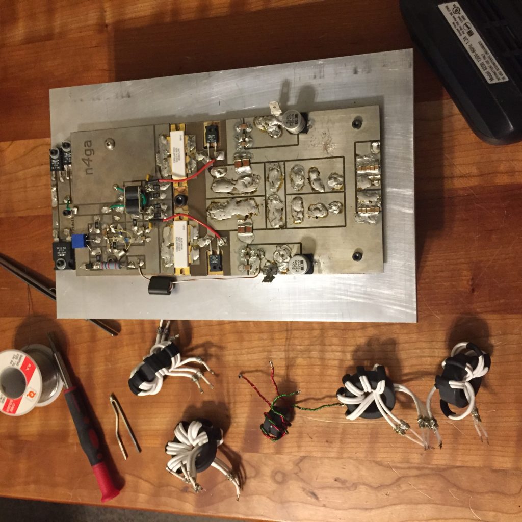
Cold Rainy Saturday here today so I decided to experiment with some TLT designs and ideas.

Some of the remaining TLTs that did not get dismantled to make others..

Stripped the TLTs off my old standby pallet, a 2 x BLF188 and went to work.

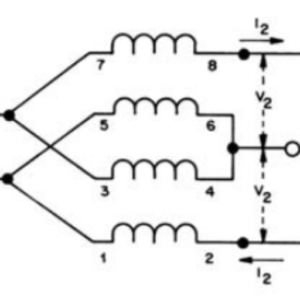
You can design TLTs using the math, but trust me, this only gets you in the ballpark – a starting point if you will.

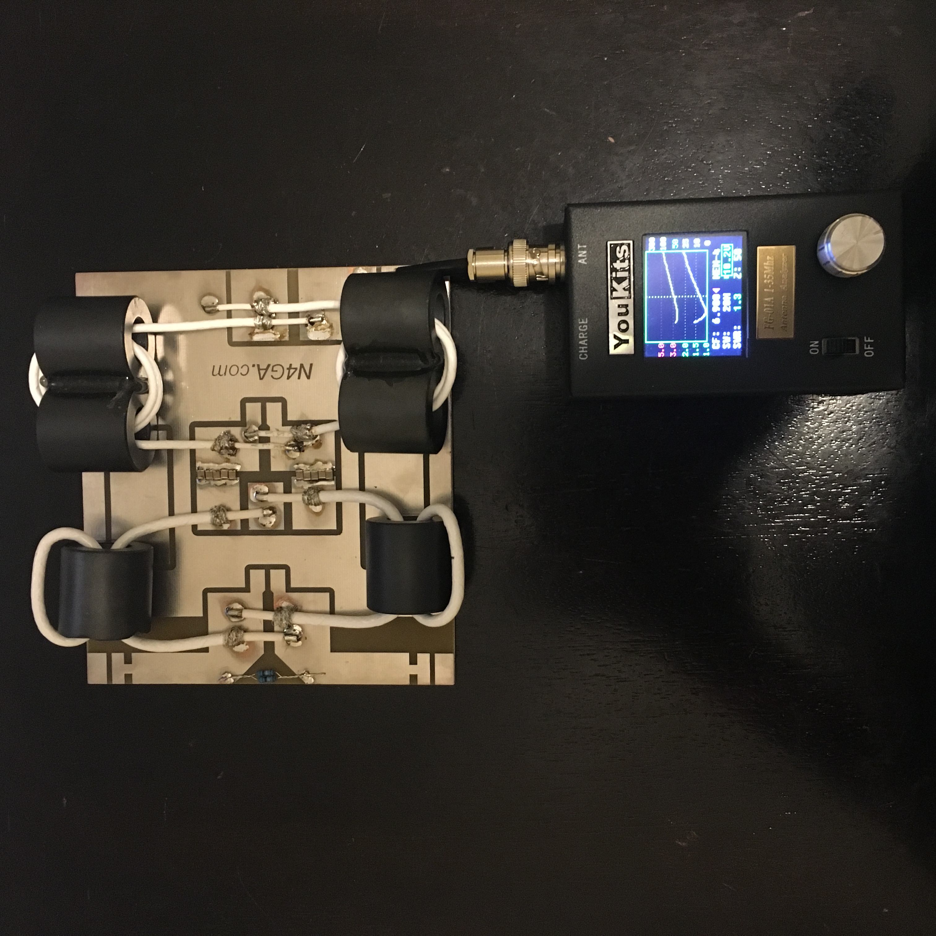
You have to add turns, remove turns, try different cores, try different coax, and each time there’s a ton of labor involved. Each time, you have to reassemble the test stand, then test the pallet across all the HF bands, 160m to 6m. This is not like pushing buttons on a simulator folks!

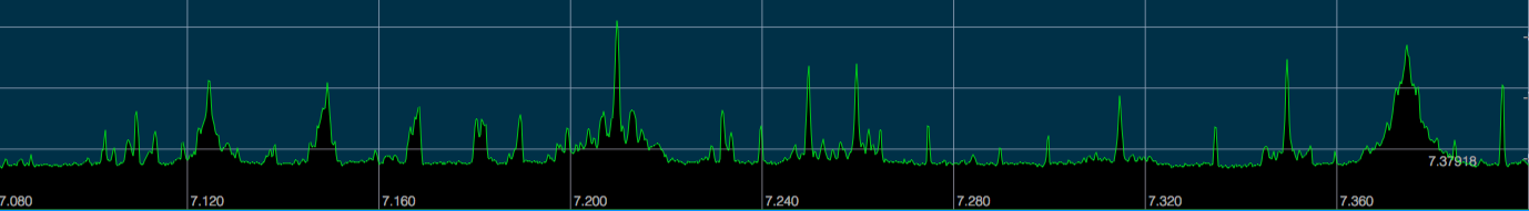
For each iteration, you put all the data in a spreadsheet, then compare it to the test before it, consider the changes made from the last test to the current test, consider what end(s) of the HF spectrum got affected and how, then make a logical adjustment for the next test.

Managed to get through about 8 permutations and with all the testing, studying the results, and then progressing logically, I ended up converging on a pretty damn nice design.

I’m going to use it in the real world for a month or so and she how it plays.


Stripped down and ready for testing

Comments

13 responses to “TLT Design and Testing”

  1. darrell wyatt Avatar
    darrell wyatt

    Well Rob are you gonna leave us in suspense? I hope you will share what you have learned brother. Course I don’t think theres anything to worry about you have been very generous with your knowledge and it is appreciated!!

  2. Mike, K4GMH Avatar
    Mike, K4GMH

    I’m like Darrell, what is the data you gathered and why did you think the a design/construct was the best?

    Thanks for sharing you experiences and data on all of your efforts with SS amps. It is very encouraging to others, like me, to give it a try – maybe one day even replacing my homemade GS35B amps, used for SO2R RTTY contesting, with a single SS amp!

    1. N4GA - Rob Avatar
      N4GA – Rob

      Mike,

      Thanks for the post. Sorry it took me so long to reply. I did not get a ping from the system telling me your post was up here.

      I have not shared anything related to TLTs because I’m still experimenting!

      I have found some good combinations of back to back 4:1 TLTs to net 16:1 but I’m not done yet. Some day if I ever “finish” this, I’ll have the info up here.

      Thanks!

  3. peter coppens Avatar

    Hi,

    The back to back principle; i don’t understand the wiring;looking for a 1 to 16 pa trafo

    Regards,

    Peter

    1. N4GA - Rob Avatar
      N4GA – Rob

      Peter,

      This is 16:1 in two 4:1 stages in series.

    2. HZ1MT Avatar
      HZ1MT

      Hi Rob,

      Im going through your blogs non stop! Its really informative and amusing to read… just a “dumb” question, what is really the advantage of using a TLT over a simple tube&sleeve output transformer? is a must to use 16:1 ratio because i’ve seen some people go with 9:1 so which ratio is more optimized for the entire HF bands?

      1. N4GA - Rob Avatar
        N4GA – Rob

        Peter,

        Lot of pieces to this so I’ll just focus on the TLT side of this. A TLT is near 100% efficient and much more broad band than a standard tube and sleeve transformer. Also, much easier to construct. The impedance ratio is not unique to either. This is more about what impedance ratio do you need, based on the power output and supply voltage you are designing for.

  4. Donald R Solberg Avatar
    Donald R Solberg

    I am building a dual BLF188XR amplifier and was planning on using a 16:1 tube and sleeve transformer. It has 61 mix torroids and HC12 coax. This is a simple design but so far I am disappointed with the test results. I can get a fairly good match from 160 to 10 meters, but the matching is very poor on 6 meters.

    I would like to have 6 meter output, so I am interested in how your 16:1 TLT tested? I was going to build the two 4:1 TLT’s in series and see if they provided a better match than the tube and sleeve.

    Do you per chance sell your PCB’s?

    73,

    Don
    K9AQ

    1. N4GA - Rob Avatar
      N4GA – Rob

      Don,

      Thanks for the note. In general, obtaining a really efficient match from 160m to 6m is very challenging. Ideally, a 6m amp would be a standalone 50Mhz amp and then you could have no compromises! But who wants two amps…

      So how do the “PROs” do it?

      First, their amps still have a compromise on 6m and most, if not all, are derated somewhat on 6m.

      Second, they use compensation capacitors (typically) at the input of the matching transformer. The value is usually obtained experimentally, since everything affects it: the PCB, the traces, the parameters of your specific output transformer, what’s after your transformer, on and on.

      This is how they “trick” the amp into playing reasonably well on 6m …. and 160m both!

      Email me if you like and I can send you a lot of pics of amp pallets with comp caps.

      Thanks!

  5. Donald R Solberg Avatar
    Donald R Solberg

    Rob,

    I have a lot of experience building 600 to 1KW amps, using VDMOS transistors. In the past I have always used 9:1 TLT’s. I am currently building a dual BLF188XR amp. I am in the process of testing multiple tube and sleeve output transformers and a TLT. I expect that the TLT will perform better but the PCB I am using is laid out for the tube and sleeve transformer.

    My primary goal is a legal limit amp (80-10 meters), with limited output on 6M. If I can get 500-600 watts on 6 meters I will consider that success.

    73,

    Don
    K9AQ

    1. N4GA - Rob Avatar
      N4GA – Rob

      That’s totally doable Don.

  6. Peter Dee Avatar
    Peter Dee

    Hi Rob, great work! I have built a w6pql sspa HF sspa using a MRF1k50. Works great (1500W) on most bands except on 160M where output is limited to 1kw and efficiency is poor. Where do I look to improve
    160 where most of my interest lies? Would switching to 43 to 77 material on tlt ferrite help on the lower bands? I don’t really care about 6M since I use a separate amp.
    Peter

    1. N4GA - Rob Avatar
      N4GA – Rob

      Peter,

      Good morning.

      Can you link me to the PQL amp you built?

      Without seeing it, in general, you need more inductance at the lower end of the range (1.8Mhz) because down there, the TLT acts like a hybrid magnetic transformer and a TLT. So it needs to be able to magnetize the ferrite somewhat.

      You have probably heard the term “minimum inductance or reactance required” related to TLTs.

      Also, the feedback circuit in these amps exists primarily to flatten the gain across the entire range. More gain exists at the low end, so it’s basically there to reduce the gain at the low end.

      So you could disconnect the feedback and carefully test the output on 160m.

      Also you could try to get more inductance at the low end on your TLTs with more turns of coax (which may degrade the top end) or a different material on the ferrites, which would not affect the top end much.

      Thank you!

      Rob

Leave a Reply

Your email address will not be published. Required fields are marked *