Transmit Receive Sequencing your Amplifier

Last year I got a lot of pings asking “where you been… why no posts… did you quit…” etc.

I get it! It’s been since May 24, 2020 since I last posted.

Well, I’m not a retired ham – still putting two kids (both engineers) through college! Also, work has gotten extremely busy this past year.

Even so, I still managed to design a little amp sequencer in 2020, and I started programming microcontrollers for some future projects.

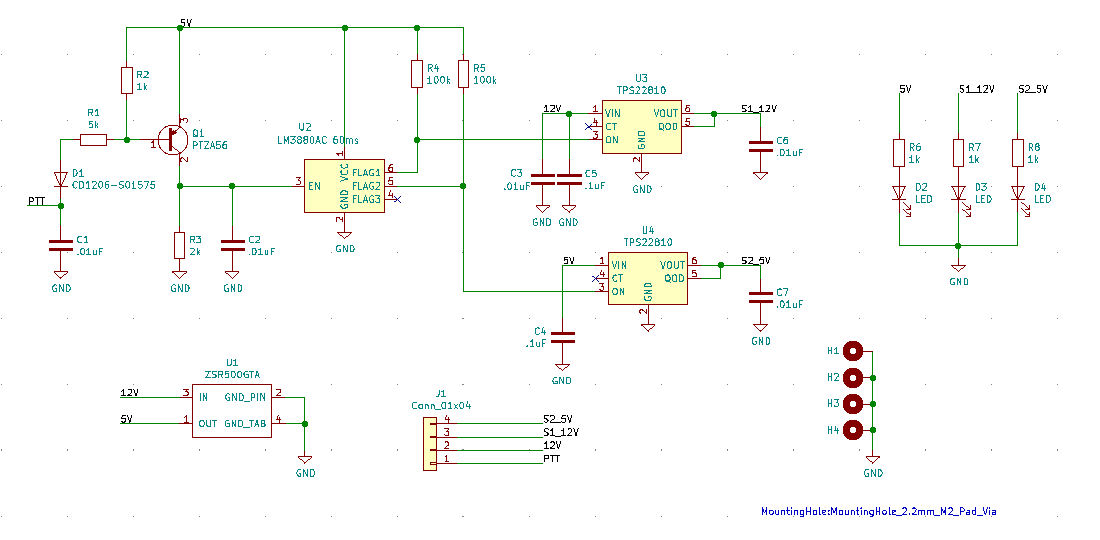
In this post, I’ll share the sequencer. Here’s the functionality:

  • The circuit is powered by 12V
  • When PTT is grounded: immediately outputs 12V to close the T/R relays
  • 60ms later, outputs regulated 5V for the LDMOS bias
  • When PTT opens: reverse of above

This of course ensures your relays never actually switch RF. They are already closed before passing RF, which is FAR different than hot-switching 1kW or more of RF.

It also provides a 60ms delay-switched 5V for your bias circuit. This makes your amp front end switching and bias circuit very simple. The boas circuit on your amp will need no relay, no regulator, no timing, nothing but a temp compensated voltage divider.

KiCAD v5.1.9 Schematic
KiCAD PCB 3D view front
KiCAD PCB 3D view back

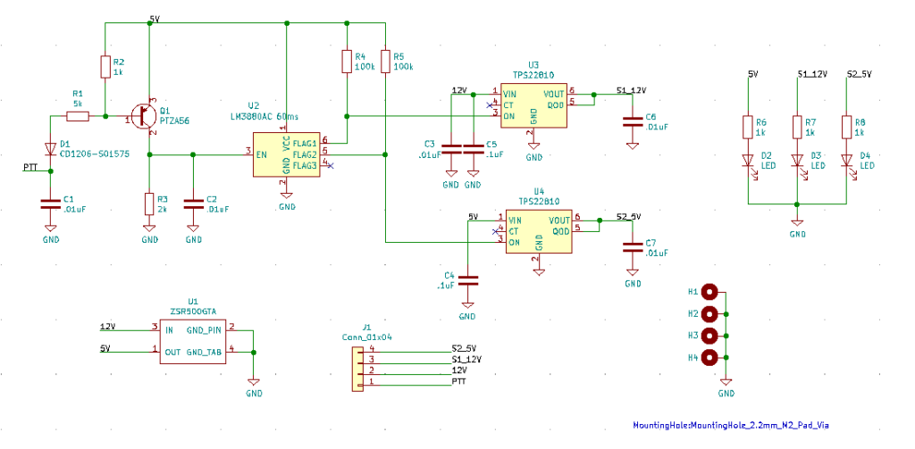
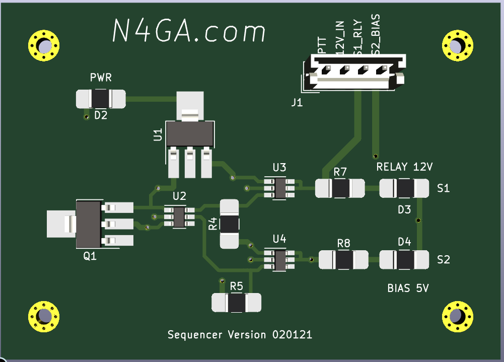
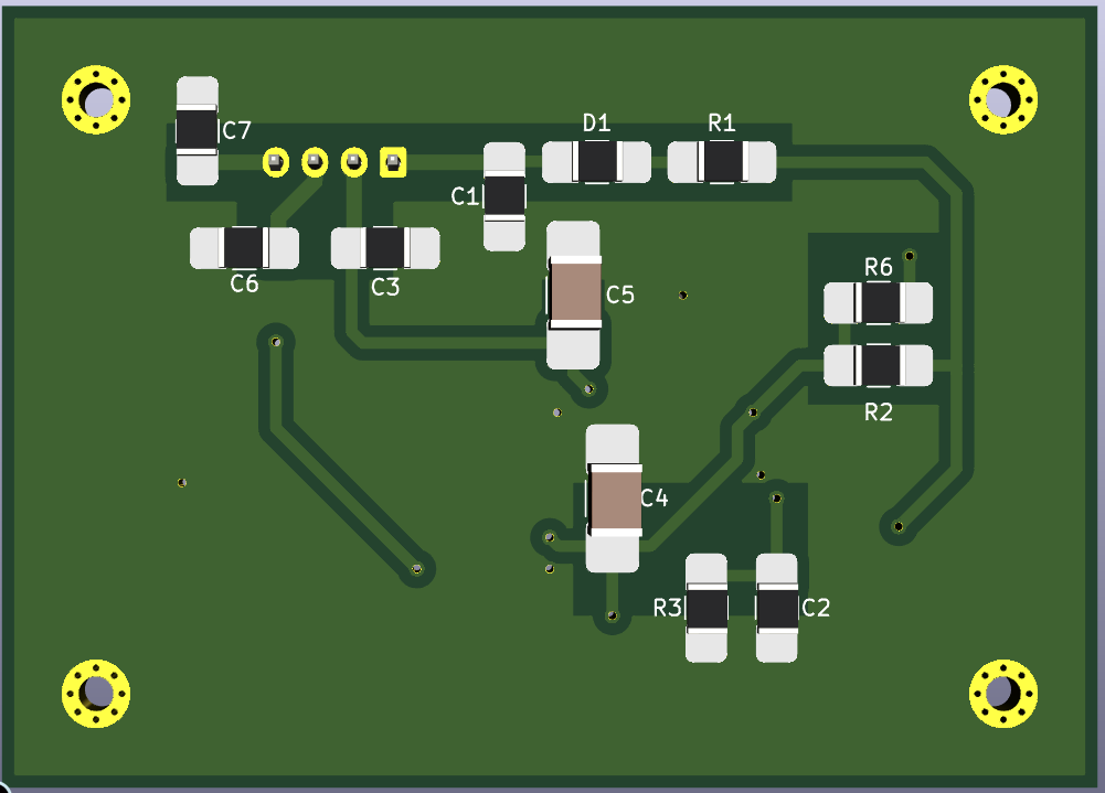
I decided to download KiCAD on my MAC and see how I liked it. Nothing like designing a PCB on a MacBook Air with zero crashes and zero slowness….all while sitting on a couch watching TV!

73, N4GA

Comments

16 responses to “Transmit Receive Sequencing your Amplifier”

  1. Vinny Stipo Avatar

    Thanks for sharing – KM2W

    1. N4GA - Rob Avatar
      N4GA – Rob

      Absolutely!

  2. Don Avatar
    Don

    Now that you’re on kicad will you make your amp designs available? Or maybe ready yet to sell bare boards? 73 Don AD7LL Cleveland Tn. Bulldogs? Gators? Bama?

    1. N4GA - Rob Avatar
      N4GA – Rob

      Don,

      If I ever get a design I like enough to sell to someone, I could see selling bare boards, or pallets, or stuffed board, or a amp kit, etc.

      You wouldn’t want to assemble this sequencer board yourself. U2, U3 and U4 are literally the size of a dimple on a golf ball! Major PITA!

      Ok, so Buccaneers, FL State, UGA

      Got two kids at UGA.

      1. Don Frasher Avatar
        Don Frasher

        Understand on the Buccaneers!
        I really hope that you do not get stuck on perfection! What I seen on your blog is already far better than anything else I have seen !
        My hope is dual device so as to achieve limit while keeping drive and harmonics low.
        Currently have ART2K0 that I would like to go with. I have a diplexer to follow behind it to help keep it clean and from bouncing back to the devices.
        More interested in the low bands, 160-20m, so lower performance above that is fine. Far to easy to use a beam or yagi on the higher frequencies. I do also have outboard thermal tracking biasing boards I could use, But anything would be better than the simple non tracking fixed voltage, or very limited thermal tracking, that I have seen in others.
        I have picked up a dual device board from DJ0ABR that looks decent, but I’m not sure if there is room for me to use 4:1 back to back(design is based on a single device 9:1) also uses a lot of through hole so the copper spreader will need some work to clear some spots.
        SO if you do get a board that your happy with I’ll be one of many in line to get it!
        Thanks for taking the time from schedule to share all of this with us.

        73
        Don AD7LL
        drfrasher@gmail.com

        1. N4GA - Rob Avatar
          N4GA – Rob

          Don,

          Thanks for the note, appreciate the compliment!

          ART2K is the current way to go I think. If you can get it fed 65V everything becomes a little easier and cleaner.

          None of these amps are going to run very linear at 1500W, the math just doesn’t work for linear class AB at 50V at that power level. What they do is slowly approach class D (square waves) so then you can get 1500W from them. You then clean up the harmonics in the LPF.

          I get a lot of requests for 2x PCBs but for the last year I’ve only been designing 1x PCBs, trying to make them very linear. So at 50V this is ~400-600W depending on frequency. At least I’ll never destroy one doing this. Ha ha!

          Thanks again and seven three!

  3. Daniel Habecker Avatar
    Daniel Habecker

    How do you like going from Altium to KiCad? I’ve tried it in the past and just got frustrated then went back to doing it in Altium. I’m sure KiCad has improved since, but how much?

    1. N4GA - Rob Avatar
      N4GA – Rob

      Dan,

      Initially any move is cludgy because you can’t find anything you need in the new software! Don’t know the hot keys, where the files are going, how the libraries and paths work, how to generate the output files, how to create a custom component, on and on.

      But after I did ONE PCB and took some notes, I find KiCAD much faster for these boards I do. Altium is good but with capability comes complexity and if you are only scratching the surface for ez RF boards like these amp boards, it just slows you down.

      Plus KiCAD is FREE and runs on my MacBook Air like a champ!

      Rob

  4. Paul Andrews Avatar
    Paul Andrews

    Very nice work.

    1. N4GA - Rob Avatar
      N4GA – Rob

      Thanks Paul! 73

  5. ITboy Avatar
    ITboy

    hello Rob and every one here!
    thanks for the answer to this topic, Rob. this home page is the top ham literature on the web about!!
    i am interested to replace the mrf 1k50 which probably broke by flashover 1:9 trasformer .
    im new user of LDMOS PA, and only 5minutes after outbox my new AMP, it go in standby with a no good white smoke….. I am studing because the problem was been into 21,mhz . The test on 10, 20, and 40 MT band was ok, with a no bad power out to the max power 1000W for few second of tx.
    On 21.3Mhz the test outputW, finished soon with only 26 A e 51volt corrent absorption also my trx give me SWR hi livel in the peak every time push the ptt. The last day was tested the LPF board using my trx only and SWRmeter and antennas and into 15mt i can see a narrow band swr with the LPF (15/17) in use than without in the line.
    Also the transistor board has the low Q in the ground of 1:9 trasformer out line than the original NPX RF 27 Mhz board with a few smd RFcapacitor of 100v that now are black and no electrolytic capacitor and a low Q inductor.
    Jiust last week i buy 2 new pallet (they are commercial and usual type but different by the first one) and a splitt combiner to make a pushpull with a low power input/output power. If my MRF k50 will broke i will change the Ldmos. The 2xART2k or the 1k6, i hope to will be a nece job to work near A class and low temperature on ssb mode………… jiust in the future value a 500W more power supply!!

    1. N4GA - Rob Avatar
      N4GA – Rob

      Sounds good! 73! N4GA

  6. Donald Waddell, K3DLW Avatar
    Donald Waddell, K3DLW

    Any chance you will share the KiCad files so I can make a board to try the Transmit Receive Sequencer? I am not afraid of the SMD components. 🙂

    1. N4GA - Rob Avatar
      N4GA – Rob

      I mailed you a couple of PCBs Don.

  7. Donald Waddell Avatar
    Donald Waddell

    Rob,

    What case code are the resistors and capacitors?

    Don
    K3DLW

    1. N4GA - Rob Avatar
      N4GA – Rob

      All resistors are 1210

      The 0.1uF caps are 1812

      The diode D1 is a 1206

      The LEDs D2 D3 D4 are PLCC-2

      The 0.01uF caps are 1210

      All that said, if you look at the PADS on the PCB, I made them all big so you can hand solder them and so you can use just about any similar sizes that fit.

Leave a Reply

Your email address will not be published. Required fields are marked *